Early Streamer Emission Air Terminal
Home » Lightning Products » Early Streamer Emission Air Terminal
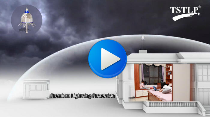
Early Streamer Emission Lightning Protection System

Previous : ESE Lightning Protection
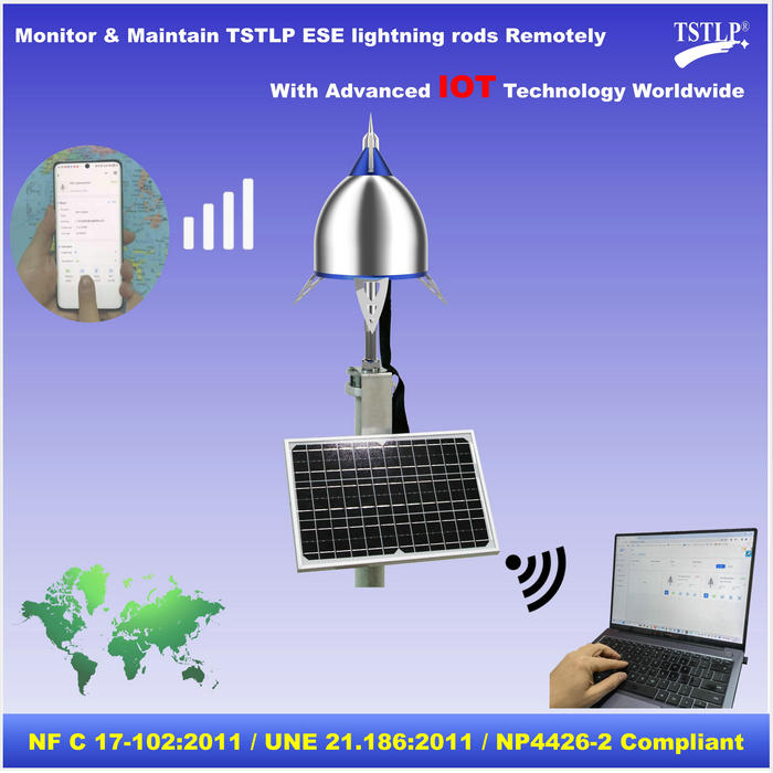
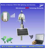
Next : Early Streamer Emission - ESE Lightning Rod with IOT Connect
Instruction
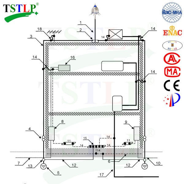
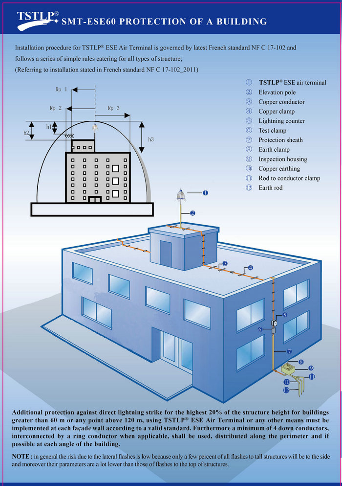
Complete TSTLP Early Streamer Emission Lightning Protection System
1- One or more TSTLP Early Streamer Emission Lightning Conductor for direct lightning protection
2- Connection component
3- One or more specific down-conductors
4- A test joint for each down-conductor
5- One earth termination for each specific down-conductor
6- Foundation earth electrode (earthing of the structure)
7- Electric power cable
8- Main electric power distribution box with SPD
9- Main telecom distribution box with SPD
10- Telecom cable with SPD
11- One or more equipotential bonding bars
12- One or more equipotential bondings between earth terminations
13- Disconnectable bonding device
14- One or more equipotential bondings (direct or via an Isolating SparkGap).
15- Main earthing bar
16- Electric equipment
17- Metallic pipe
18- One or more equipotential bondings through a spark gap for aerial mast
1) Design
Based on the necessary lightning protection level, a design should be made to determine the lightning conductor placement, the down-conductors paths and the location and type of the earth termination system.
This design should be based on available data and including:
- shape and slope of the roofs;
- material of the roof, walls and internal structure;
- metallic parts of the roof and important external metallic elements such as gas ducts, air condition in gequipment, ladders, aerials, water tanks,…
- gutters and rainwater pipes;
- prominent parts of the structure and the material they are made (conductive or not);
- most vulnerable parts of the structure : the structural points considered as vulnerable are the prominent parts, particularly towers, weathervanes, sharp objects, chimneys, gutters, edges andridges, metallic objects (air extractors, wall cleaning systems, rails,photovoltaic cells (UTE C 15-712-1), balustrades, …), staircases, equipment rooms on flat roofs, etc.;
- positioning of the metallic ducts (water, power, gas…) of the structure;
- nearby obstacles that may influence the trajectory of the lightning discharge, such as overhead power lines, metallic fences, trees, etc.;
- the characteristics of the environment, that may be particularly corrosive (salty environment,petrochemical or cement factory, etc.;
- presence of flammable material or sensitive equipment such as computers or electronic equipment, high value or irreplaceable goods, etc..
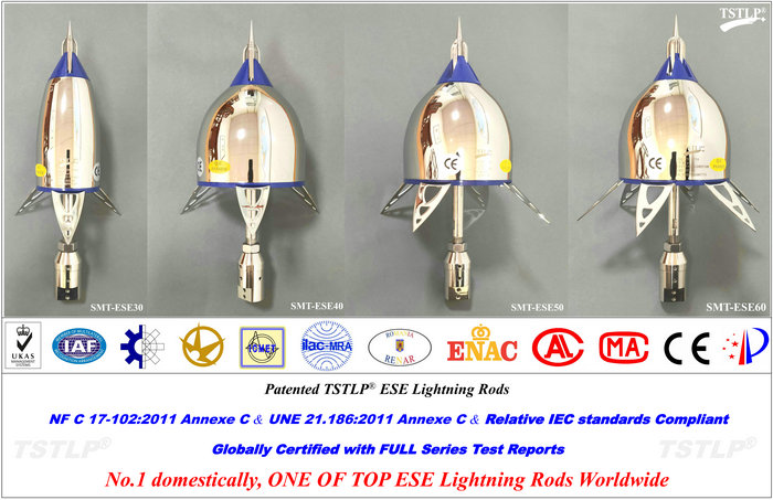
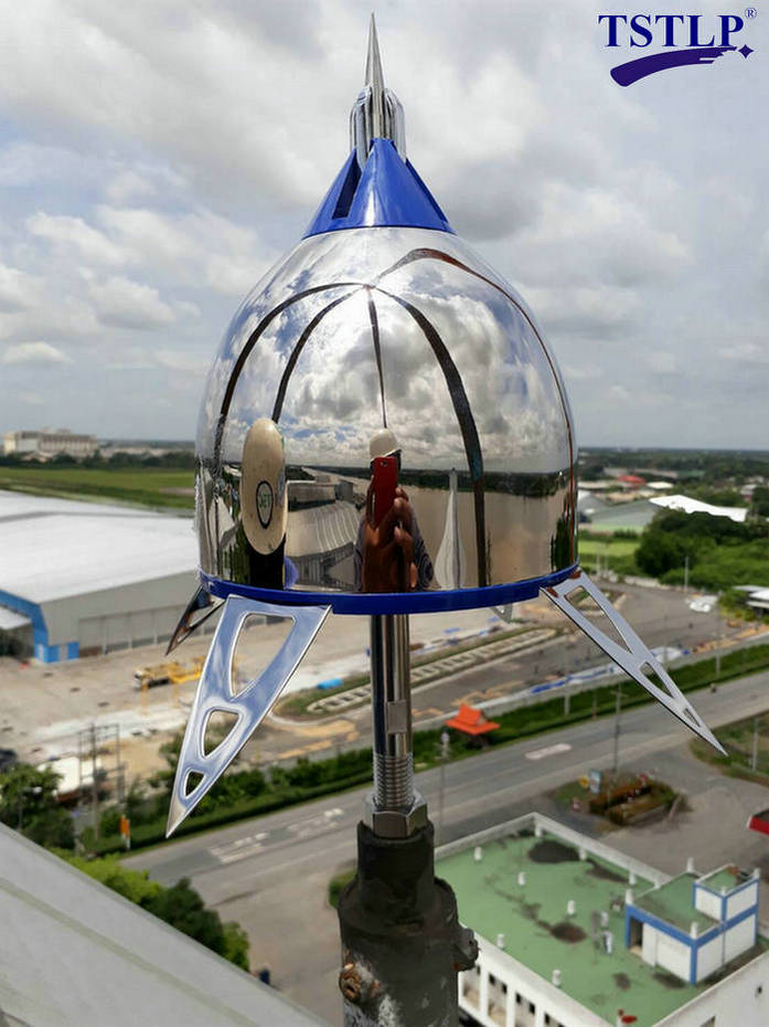
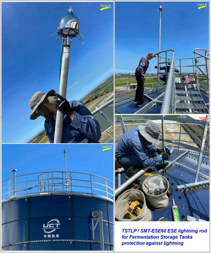
2) Early Streamer Emission Lightning Conductor
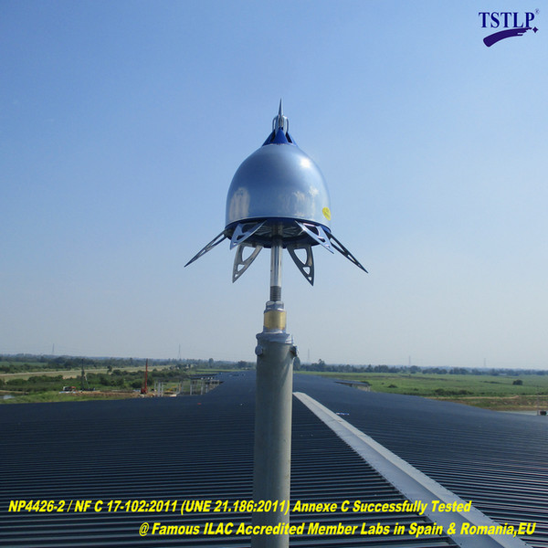
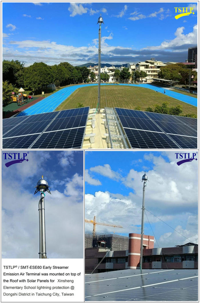
2.1) An Early Streamer Emission Lightning Conductor (ESELC) is composed of one striking point, emission device and a fixing element and a connection to the down-conductors. The area protected by an ESELC is determined according to its efficiency as defined in Clause 2.2.The ESELC should preferably be installed on the highest part of the structure. It shall be the highest point within the area to be protected.
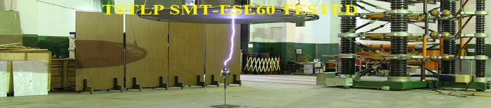
2.2) An ESELC is characterized by its efficiency ΔT which is proved in the evaluation test (see Annexe C).The maximum value for ΔT, whatever are the test results, is 60 μs.
2.3) Positioning of the ESELC
2.31)Protected area.
The protected area is delineated by a surface of revolution defined by the protection radii corresponding to the different considered heights h and which axis is the same as the one of the lightning conductor
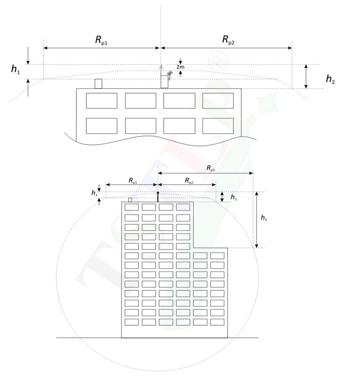
where:hn is the height of the ESELC tip over the horizontal plane through the furthestpoint of the object to be protected
Rpn is the ESELC protection radius to the considered height hn.
Figure 2 – Protection Radii (with hypothesis h1 = 5 m)
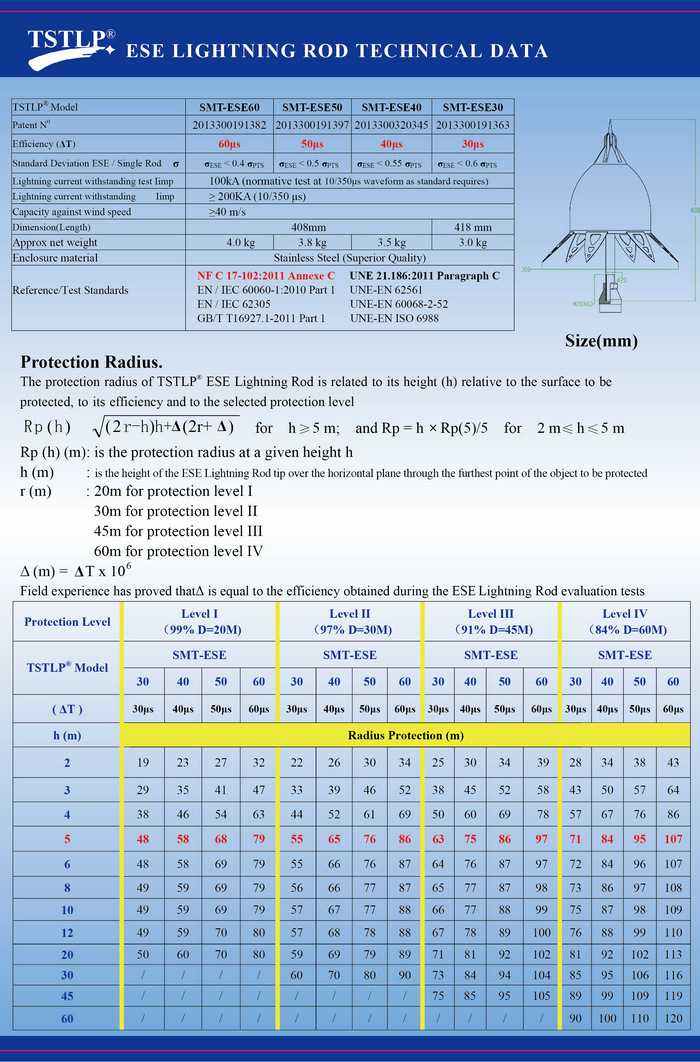
2.32)Protection radius
The protection radius of TSTLP® Early Streamer Emission Lightning Conductor is related to its height (h) relative to the surface to be protected, to its efficiency and to the selected protection level
for h ≥ 5 m; 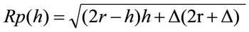 and
and
Rp = h × Rp(5)/5 for 2 m ≤ h ≤ 5 m
Rp (h) (m): is the protection radius at a given height h
h (m) : is the height of the ESE lightning conductor tip over the horizontal plane through the furthest point of the object to be protected
r (m) : 20m for protection level I
30m for protection level II
45m for protection level III
60m for protection level IV
Δ (m) = ΔT x 106
Field experience has proved that Δ is equal to the efficiency obtained during the ESE lightning conductor evaluation tests
2.3.3) Selection and positioning of the ESELC
For the installation of each lightning protection system, a risk analysis must be made in order todetermine the minimum required lightning protection level.
The positioning of the ESELC is chosen according to 2.1) and 2.35.
The required protection radii to protect the structure are determined according to the features of thebuilding.
Both height of the ESELC and its efficiency are determined using the points and formulas cited above based on the selected ESELC 2.3.4)
2.3.4)Protection of high rise buildings (height greather than 60 m)
Additional protection against direct lightning strike for the highest 20% of the structure height for buildings greater than 60 m or any point above 120 m, using ESELC or any other means must be implemented at each façade wall according to a valid standard. Furthermore a minimum of 4 down conductors, interconnected by a ring conductor when applicable, shall be used, distributed alongthe perimeter and if possible at each angle of the building.
NOTE : in general the risk due to the lateral flashes is low because only a few percent of all flashes to tall structures will be tothe side and moreover their parameters are a lot lower than those of flashes to the top of structures.
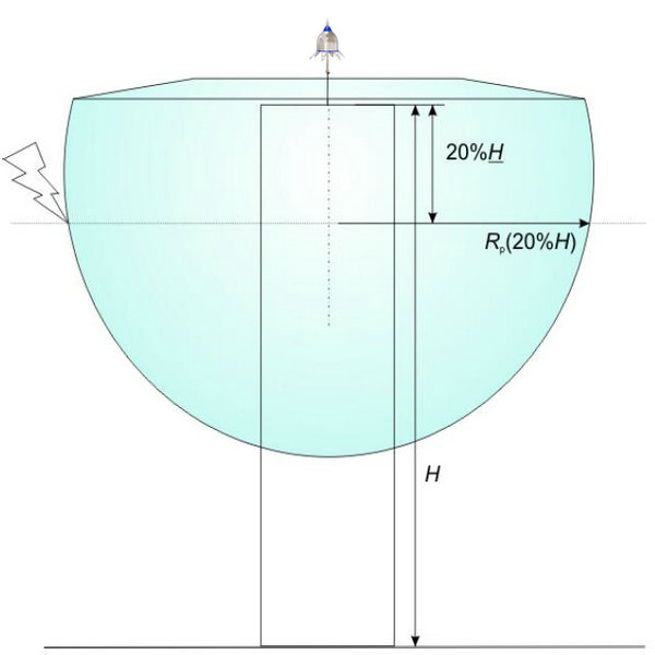
Figure 3 - Additional protection against direct lightning strike for the highest 20% of the structure height for buildings taller than 60 m
2.3.5)Protection of buildings for levels of protection I+ and I++
Level of protection I+ : the ESE System at level of protection 1 is additionnaly connected to the metal structure or reinforced bars of the buildings used as natural down conductors in addition to the dedicated down conductors included in the ESE System according to 3) Connection to the natural down conductors shall be made at roof level and ground level. When the dowconductors are not interconnected at rooflevel, a ring conductor located above the roof can be used to achieve these requirements. Thedownconductors shall be interconnected at ground level either by the earthing loop or by a dedicated conductor.
If there is no natural down conductors or if one of the above requirements cannot be fulfilled, level I+cannot be achieved.
Level of protection I++ : the roof is protected at level I+ with an ESELC having a radius of protection reduced by 40% compared to values given in 2.3.2) to achieve a complete protection of equipments onthe roof against direct lighning strikes.
2.4)Materials and dimensions.
All materials should comply with EN 50164-2
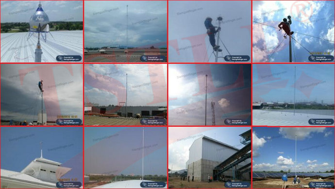
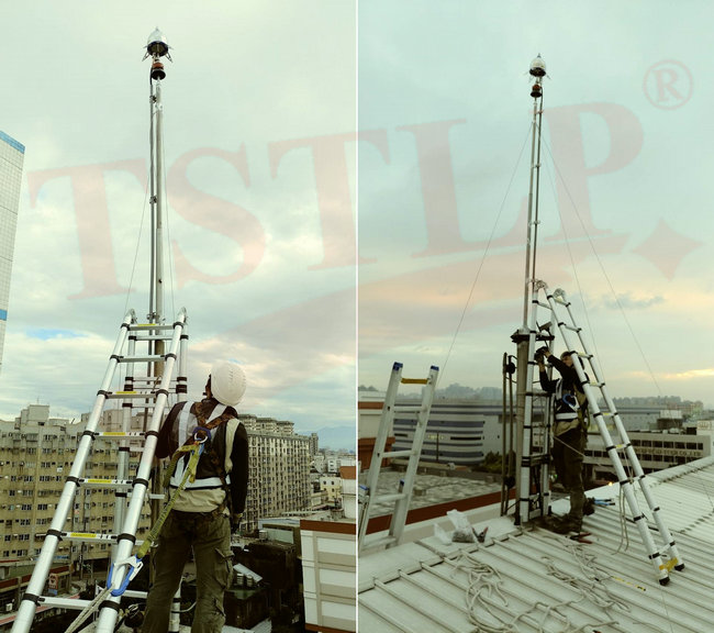
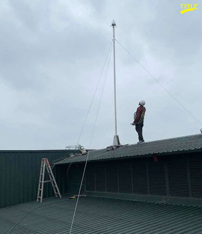
2.5)Installation
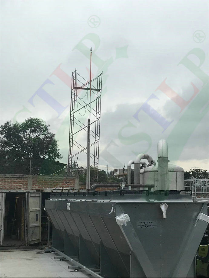
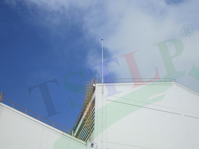
The top of the ESELC shall be installed at least 2 m over the area that it protects, including aerials,refrigerating towers, roofs, tanks, etc.
When designing the ESE System, it is recommended to take into account the architectural spots that areadequate to place an ESELC. These locations are high structural points like:
- rooms on the terraces;
- ridge;
- masonry or metallic chimneys.
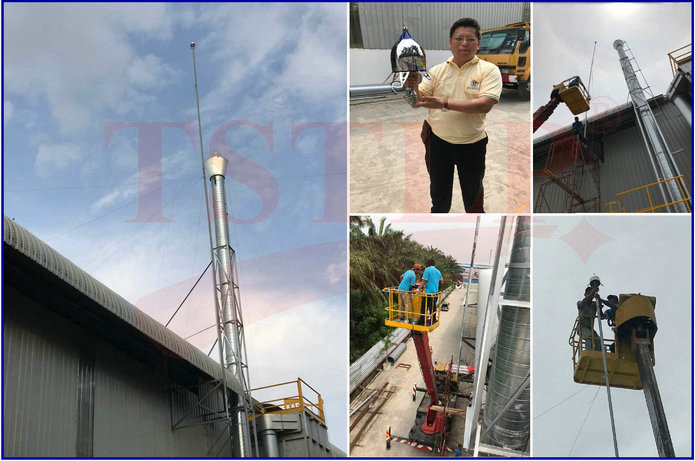
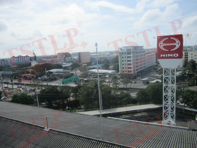
Those ESELC protecting open areas (sport fields, golf, swimming pools, campsites, etc.) will be installedover specific supports such as lightning masts, poles or any other nearby structure that allows the ESEAT to cover the whole area to be protected.
ESELC can occasionally be placed over free-standing masts. In case of using conductive guy wires, they will be bonded, at the anchoring point on the ground, to the down-conductors using conductors according to EN 50164-2.
3) Down Conductors ...
4) Equipotential bonding of metal parts ...
5) Lightning equipotential bonding ...
6) Earth termination systems ...
7) Special measures ...
8) Execution file, vérification and maintenance ...
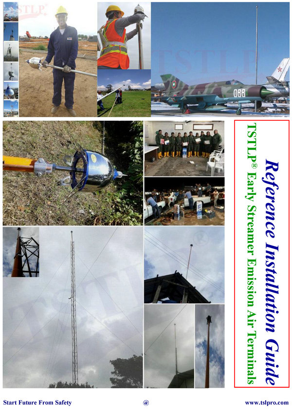
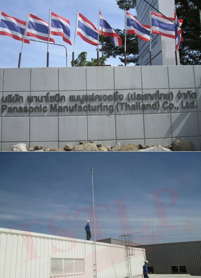
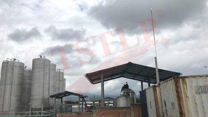
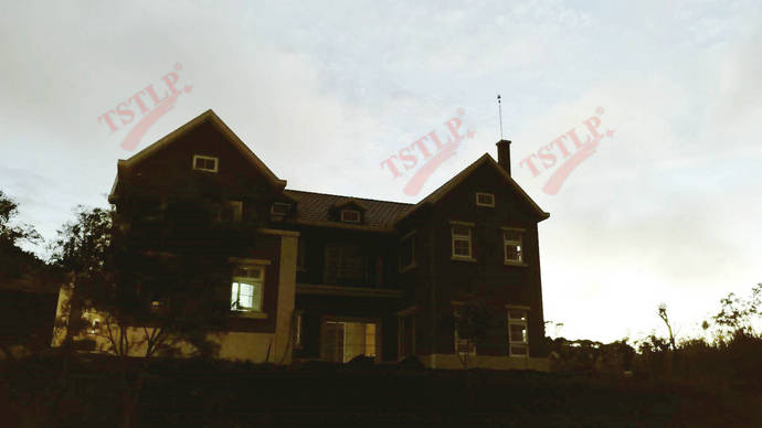
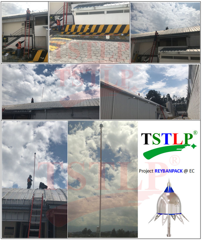
Part of our International (Project) References: https://www.tslpro.com/references-4.html
- CONTACT US
 0086 13926098193
 0086 20 28819702 EXT 27806
 [email protected]
 Hongdiyuan Industrial Park, Wufeng Avenue, Linjiang Town, Jiangdong New District, Heyuan, Guangdong,P.R.C.
 http://www.tslpro.com
 +86 13926098193
 F13926098193
 tslpro.tstlp
-


